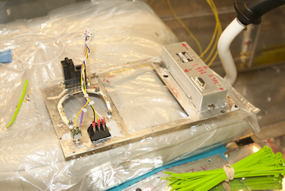
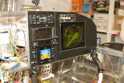
The center panel was next. The first two pictures show it being wired up and installed. I added a molex connecter here since the TO/GA switch had solder terminals. This allows me to easily disconnect the TO/GA and flap switches.
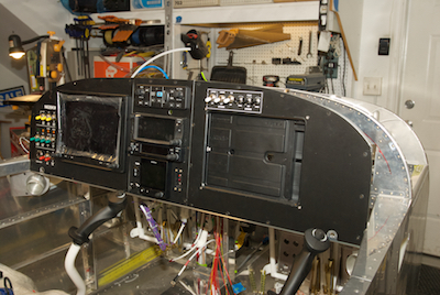
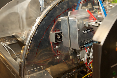
Then I put in the last panel and started on all of the switches. The last pictures shows another customization I added. I located three spots for bridge rectifiers that would allow me to provide redundant power to the three instruments that didn’t come with that capability built in. This picture shows the location without heat sinks.